|
|
CHAPTERS
This objective of this page is to offer a basic insight into the major systems that make up our cars.I hope to constantly update this page on a regular basis. 1 The Electrical System Active 2 The Engine..Brief Summary Active
3 Volvo 850 and the Turbocharger Active
4 Suspension Systems Not Active
5 Fuel Systems Not Active
6 Cooling Systems Not Active
7 Brake Systems Active
8 Drive Train Systems Not Active
9 Diesel Systems Not Active
10 Exhaust Systems Not Active
11 Accessory Systems(air con...GPS etc) Not Active
THE ELECTRICAL SYSTEM
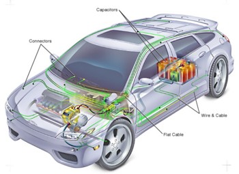
In the beginning,the automotive industry used electricity only to ignite the fuel inside the engine. By the late 1920's, the electric starter replaced the hand crank, electric headlights made acetylene lamps obsolete and electric horns drowned out the squeak of the hand-squeezed air horn. Today, modern cars require an elaborate electrical system of circuits just to produce, store, and distribute all the electricity it requires simply for everyday operation.
The first major component in the electrical system is the battery. The battery is used to store power for starting, and for running auxiliary devices such as clocks, radios and alarms when the engine is off. The next major component is the starter motor, which is used to start the engine. The third component is a charging device powered by the engine, known as the alternator. It powers the electrical system when the car is running, and restores the charge within the battery. With these basic components, the car maintains its supply of electricity. A device called the voltage regulator keeps the power level stabilized, and the fuse box keeps minor problems from becoming major ones.
Many different auxiliary electrical devices are used in modern cars, such as: radios, cellular phones, rear window defrosters and electric door locks, as well as a vast array of motors powering everything from the sunroof to GPS systems.
Battery
The car's initial source of electricity is a battery, whose most important function is to start the engine. Once the engine is running, an alternator takes over to supply the car's electrical needs and to restore energy to the battery.
A 12-volt storage battery consists of layers of positively and negatively charged lead plates that, together with their insulated separators, make up each of six two-volt cells. The cells are filled with an electricity-conducting liquid (electrolyte) that is usually two-thirds distilled water and one-third sulfuric acid. Spaces between the immersed plates provide the most exposure to the electrolyte. The interaction of the plates and the electrolyte produces chemical energy that becomes electricity when a circuit is formed between the negative and positive battery terminals.
Starter
The starter converts electricity to mechanical energy in two stages. Turning on the ignition switch releases a small amount of power from the battery to the solenoid above the starter. This creates a magnetic field that pulls the solenoid plunger forward, forcing the attached shift yoke to move the starter drive so that its pinion gear meshes with the engine's crankshaft flywheel. When the plunger completes its travels, it strikes a contact that permits a greater amount of current to flow from the battery to the starter motor. The motor then spins the drive and turns the meshed gears to provide power to the crankshaft, which prepares each cylinder for ignition. After the engine starts, the ignition key is released to break the starting circuit. The solenoid's magnetic field collapses and the return spring pulls the plunger back, automatically shutting off the starter motor and disengaging the starter drive.
When the starter is not in use, the drive unit is retracted so that its pinion is disengaged from the flywheel. As soon as the starter is activated, the forward movement of the solenoid plunger causes the shift yoke to move the drive in the opposite direction and engage the pinion and flywheel. The pinion is locked to its shaft by a clutch that unlocks if the engine starts up and the flywheel begins turning the pinion faster than its normal speed. By allowing the pinion to spin freely for a moment, the clutch protects the motor from damage until the drive is retracted.
Alternator or Generator
The alternating-current generator, or alternator, is the electrical system's chief source of power while the engine is running. Its shaft is driven by the same belt that spins the fan. It converts mechanical energy into alternating-current electricity, which is then channeled through diodes that alter it to direct current for the electrical system and for recharging the battery.
Lighting Circuit
The automobile lighting circuit includes the wiring harness, all the lights, and the various switches that control their use. The complete circuit of the modern passenger car can be broken down into individual circuits, each having one or more lights and switches. In each separate circuit, the lights are connected in parallel, and the controlling switch is in series between the group of lights and the fuse box. The parking lights, are connected in parallel and controlled by a single switch. In some installations, one switch controls the connection to the fuse box, while a selector switch determines which of two circuits is energized. The headlights, with their upper and lower beams, are an example of this type of switch. Again, in some cases, such as the courtesy lights, several switches may be connected in parallel so that any switch may be used to turn on the lights.
Main Lighting Switch
The main lighting switch (sometimes called the headlight switch) is the heart of the lighting system. It controls the headlights, parking lights, side marker lights, taillights, license plate light, instrument panel lights, and interior lights. Individual switches are provided for special purpose lights such as directional signals, hazard warning flashers, back up lights, and courtesy lights. The main lighting switch may be of either the "push-pull" or "push-pull with rotary contact" types. A typical switch will have three positions: off, parking, and headlamps. Some switches also contain a rheostat to control the brightness of the instrument panel lights. The rheostat is operated by rotating the control knob, separating it from the push-pull action of the main lighting switch.
When the main lighting switch completes the circuit to the headlamps, the low beam lights the way for city driving and for use when meeting oncoming traffic on the highway. When the dimmer switch is actuated, the single filament headlamps go "on," along with the high beam of the two filament headlamps. The next actuation of the dimmer switch returns the headlighting system to low beams only on the two filament lamps. Some cars are equipped with an electronic headlight dimming device, which automatically switches the headlights from high beam to low in response to light from an approaching vehicle or light from the taillight of a vehicle being overtaken. The dimmer switch in the automatic headlamp dimming system is a special override type. It is located in the steering column as part of a combination dimmer, horn, and turn signal switch. The override action occurs when a slight pull toward the driver on the switch lever provides high beam headlights regardless of the amount of light on the sensor-amplifier.
For some years there has been discussion about the advantages of a polarized headlight system. Such a system comprises headlights which produce polarized light in a particular plane. The windscreens of all cars would be fitted with polarizing glass, which would be oriented so that glare from an approaching vehicle would be essentially eliminated, while the forward vision would still be kept at the present levels. The advantages the system appear attractive, but the practical problems of making the transition are very great, since it would not be practical to convert all existing vehicles to this type of lighting. Also, any benefits would only be marginal because glare itself is not a frequent cause of accidents. However, many cars now have refracting or colored glass to cut down on glare.
Due to recent legislation, newer cars in Texas with the dimmer switch mounted on the steering column will have to be refurbished with standard floor-mounted dimmers. Too many Aggies are being found in the ditch with their legs caught in the steering wheel.
Directional Signal Switch
The directional signal switch is installed just below the hub of the steering wheel. A manually controlled lever projecting from the switch permits the driver to signal the direction in which he wants to turn. Moving the switch handle down will light the "turn signal" lamps on the left front and left rear of the car, signaling a left turn. Moving the switch upward will light the turn signal lamps on the right (front and rear), signaling a right turn. With the switch in a position to signal a turn, lights are alternately turned "on" and "off" by a turn signal flasher. Incorporated in the directional signal switch is a "lane change switch mechanism." This feature provides the driver the opportunity to signal a lane change by holding the turn lever against a detent, then releasing it to cancel the signal immediately after the maneuver is completed.
Stoplight Switch
In order to signal a stop, a brake pedal operated "stoplight switch" is provided to operate the vehicle's stop lamps. In addition to lighting the conventional rear lights, the switch also operates the center high-mounted stop lamp, that became mandatory on later models. Cruise control equipped vehicles may also utilize a vacuum release valve. In this case, both the vacuum release valve and the stoplight switch are actuated by movement of the brake pedal.
Horn
The car horn on passenger cars provides the driver with a means of sounding an audible warning signal. The horn electrical circuit generally includes: battery, fuse or fusible link, horn relay, horn(s), steering column wiring harness, horn switch, and body sheet metal. Often, a cadmium plated screw is used to ground the horn to the body of the vehicle. Horns usually are located in the forward part of the engine compartment or in the front fender well. The horn switch is built into the steering wheel or incorporated into the multi-functional switch lever, which includes turn signal and dimmer switch.
Electricity At Rest
The ancient Greeks had a word for it. Records show that as early as 600 BC the attractive properties of amber were known. Thales of Miletus (640-546 BC), one of the "seven wise men" of ancient Greece, is credited with having observed the attraction of amber for small fibrous materials and bits of straw. Amber was used by these people, even as it is now, for ornamental purposes. Just as the precious metals had their names of gold and silver, so amber had its name: "electron." It was later shown that the same effect can be obtained by rubbing a rod of glass or hard rubber with a handkerchief. Many other nonmetallic materials are found to have this property, which is known as "static electricity."
All electrified materials behave either as glass or rubber. Glass has a "positive" charge and hard rubber has a "negative" charge. If you electrify two strips of hard rubber by rubbing them with fur, they will repel each other. Two glass rods will behave the same way. But, if you electrify a rod of rubber and suspend it near an electrified rod of glass, they will attract each other. One of the most important laws of electricity is "Bodies with similar charges repel each other; bodies with opposite charges attract each other." A positive charge is designated with a (+); a negative charge by the sign (-).
Although people have controlled electricity for many years, no one can explain exactly what it is. Many different theories have been given as to the nature of electricity through the years, but the modern one is the "Electron theory." In short, the electron theory proposes that all matter consists of tiny particles called molecules. These molecules are made up of two or more smaller particles called atoms. The atoms are then divided into smaller particles called protons, neutrons, and electrons. These particles are all the same in matter, whether in gas, liquid, or solid. The different properties or characteristics of the matter take form according to the arrangement and numbers of these particles which make up the atom. The proton has a natural positive charge of electricity; the electron has a negative charge; and the neutron has no charge at all, but just adds weight to the matter.
Protons and neutrons form the central core of the atoms about which the electrons rotate. The electrons carry small negative charges of electricity, which neutralize the positive charges of the protons. The simplest atom of all is the hydrogen atom. It consists of one positive proton and one negative electron. Other atoms, such as those forming copper, iron, or silicon, are much more complicated. Copper, for example, has 29 electrons circling about its nucleus in four different orbits. While protons are much smaller than electrons in size, they contain the bulk of the mass of every atom. One proton, for example, weighs nearly two thousand times as much as an electron. The electrons therefore are light particles or objects around a small but relatively heavy nucleus.
It is difficult to conceive the size of the atom. Research by physicists has established that the mass on one electron is about .000,000,000,000,000,000,000,000,000,911 of a gram. If you assume that one proton in a hydrogen atom is the size of a baseball in Kansas City, then the electron would have an orbit which would reach from the Atlantic coast to the Pacific. Along with the extremely small size of electrons and protons, they are separated by relatively vast distances.
Conductors and Insulators
Not all substances are good conductors of electricity. As a general rule, metals are good conductors whereas nonmetals are poor conductors. The poorest of conductors are commonly called "insulators," or "nonconductors." Aluminum, copper, gold, iron, mercury, nickel, platinum, and silver are examples of good conductors. Amber, glass, mica, paper, porcelain, rubber, silk, and sulfur are all nonconductors. The difference between a conductor and an insulator is that in a conductor, there are free electrons, whereas in an insulator, all of the electrons are tightly bound to their respective atoms. In an uncharged body, there are an equal number of positive and negative charges. In metals, a few of the electrons are free to move from atom to atom, so that when a negatively charged rod is brought to the end of the conductor, it repels nearby free electrons in the conductor, causing them to move. They in turn repel free electrons in front of them, giving rise to a flow of electrons all along the conductor. There are a large number of substances that are neither good conductors of electricity nor good insulators. These substances are called "semi-conductors." In them, electrons are capable of being moved only with some difficulty, i.e., with considerable force.
Electricity In Motion (Electrical Current)
When an electric charge is at rest it is spoken of as "static electricity," but when it is in motion, it is referred to as an "electric current." In most cases, an electric current is described as a flow of electric charge along a conductor. To make an electron current flow continuously along a wire, a continuous supply of electrons must be available at one end and a continuous supply of positive charges at the other. This is like the flow of water through a pipe: to obtain a continuous flow, a continuous supply of water must be provided at one end and an opening for its escape into some receptacle at the other. The continuous supply of positive charge at the one end of a wire offers a means of escape for the electrons. If this is not provided, electrons will accumulate at the end of the wire and the repulsion back along the wire will stop the current flow.
The rate at which the free electrons drift from atom to atom determines the amount of electrical current. In order to create a drift of electrons through a circuit, it is necessary to have an electrical pressure, or "voltage." Electric current, then, is the flow of electrons. The more electrons in motion, the stronger the current. In terms of automotive applications, the greater the concentration of electrons at a battery or generator terminal, the higher the pressure between the electrons. The greater this pressure (voltage) is, the greater the flow of electrons.
In modern electric car designs, the drive motors are often used as the brakes also, allowing them to switch over into performing as generators, which charge the batteries with the energy generated.
Electromagnetic Principles
The connection between electricity and magnetism was made by Oersted, a Danish scientist, in 1820. He had frequently demonstrated the nonexistence of a connection between electricity and magnetism. His usual procedure was to place a current-carrying wire at right angles to, and directly over, a compass needle to show that there was no effect of one on the other. One occasion, at the end of his lecture, he placed the wire parallel to the compass needle and saw the needle move to one side. When he reversed the current in the wire, the needle, to his amazement, deviated in the opposite direction. Thus a great discovery concerning electromagnetism was made quite by accident.
There is no actual knowledge as to why some materials have magnetic properties and others have not. The "electron theory" generally is accepted as the best explanation of magnetism. It is also known as the "domain theory."
According to the theory, an electron moving in a fixed circular orbit around the proton creates a magnetic field with the north pole on one side of the orbit and a south pole on the other side. It is assumed that the orbiting electron carries a negative charge of electricity, which is the same as electrical current flowing through a conductor. Current flow, then, is from negative to positive. When a number of magnetized orbiting electrons exist in a material, they interact with each other and form "domains," or groups of atoms having the same magnetic polarity. However, these domains are scattered in random patterns throughout and the material is, in effect, demagnetized. Under the influence of a strong external magnetic field, domains become aligned and the total material is magnetized. The strength of its magnetic field depends on the number of domains that are aligned. In magnetic substances, the domains align themselves in parallel planes and in the same direction when placed in a magnetic field. This arrangement of the electron-created magnets produces a strong magnetic effect.
If you stroke a piece of hardened steel with a magnet, the piece of steel itself will become a magnet. (Steel railroad tracks laid in a north-to-south direction become magnetized because they lie parallel to the magnetic lines of the earth.) Much stronger magnets and magnetic fields can be produced by electrical means. Placing a piece of steel in any strong magnetic field will cause it to become magnetized.
A magnetized field surrounds any conductor carrying an electrical current. The discovery of that fact resulted in the development of much of our electrical equipment. The "field of force" is always at right angles to the conductor. Since the magnetic force is the only force known to attract a compass needle, it is obvious that a flow of electric current produces a magnetic field similar to that produced by a permanent magnet. Not only is the field of force at right angles to the conductor, but the field also forms concentric circles about the conductor. When the current in the conductor increases, the field of force is increased. Doubling the current will double the strength of the field of force.
The Left-Hand Rule (Magnetic Effect)
Oersted's experiment has been interpreted to mean that "around every wire carrying an electric current there is a magnetic field." The direction of this field at every point, like that around a bar magnet, can be mapped by means of a small compass or by iron filings. If a wire is mounted vertically through a hole in a plate of glass or other suitable nonconductor, and then iron filings are sprinkled on the plate, there will be a lining-up of the filings parallel to the magnetic field. The result shows that the magnetic lines of force or "lines of induction" are concentric circles whose planes are at right angles to the current.
The "left-hand rule" used in electromagnetism can always be relied upon to give the direction of the magnetic field due to an electron current in a wire. Derived from experiment, the rule states: "if the current-carrying wire were to be grasped in the left hand, the thumb pointing in the direction of the electron current, negative (-) to positive (+), the fingers will point in the direction of the magnetic induction."
Magnetic Properties of A Solenoid
Shortly after Oersted discovered the magnetic effect of a current-carrying wire, Ampere found that a loop or coil of wire (a single loop or a coil of several turns of wire) acted as a magnet. A coil of wire of this kind is sometimes referred as a "solenoid," or as a "helix." The magnetic lines of force in a solenoid are such that one side or end of the coil acts like a "N" magnetic pole and the other side or end like a "S" magnetic pole. At all points in the region around a coil of wire carrying a current, the direction of the magnetic field, as shown by a compass, can be predicted by the left-hand rule. Inside each loop or turn of wire, the lines point in one direction, whereas outside they point oppositely. Outside the coil, the lines go the same way they do about a permanent bar magnet, whereas inside the coil they go from "S" to "N". Not only does one coil of wire act like a magnet, but two coils will demonstrate the repulsion and attraction of like and unlike poles.
Electronics (Solid State)
Electronics refers to any electrical component, assembly, circuit, or system that uses solid state devices. "Solid state" means that these devices have no moving parts, other than electrons. Examples of solid state devices include semiconductor diodes, transistors, and silicon controlled rectifiers. These and many more have broad application in automotive electronics.
Semiconductors and Diodes
Semiconductors are made from material somewhere between the ranges of conductors and nonconductors. Semiconductors, basically, are designed to do one of three things: (1) stop the flow of electrons, (2) start the flow of electrons, or (3) control the amount of electron flow. A semiconductor diode is a two-element solid state electronic device. It contains what is termed a "P" type material connected to a piece of "N" material. The union of the "P" and "N" materials forms a PN junction with two connections. The "anode" is connected to the P material; the "cathode" is connected to the N material. A diode is, in effect, a one-way valve. It will conduct current in one direction and remain non conductive in the reverse direction. When current flows through the diode, it is said to be "forward biased." When current flow is blocked by the diode, it is "reverse biased." When a diode is reverse biased, there is an extremely small current flow; actually, the current flow is said to be "negligible." When the P and N are fused together to form a diode, it can be placed in a circuit. The P material is connected to the positive side of the battery and the N material is connected to the negative side of the battery. Connected in this manner, current will flow. If connected in the reverse manner, current will not flow.
Transistors and Resistors
A transistor is a solid state device used to switch and/or amplify the flow of electrons in a circuit. A typical automotive switching application would be a transistorized ignition system in which the transistor switches the primary system off and on. An amplifying application could be in a stereo system where a radio signal needed strengthening.
A transistor is a three-element device made of two semiconductor materials. The three elements are called "emitter," "base," and "collector." The outer two elements (collector and emitter) are made of the same material; the other element (base) is different. Each has a conductor attached. The materials used are labeled for their properties: "P" for positive, meaning a lack of electrons. It has "holes" ready to receive electrons. "N" is for negative, which means the materials has a surplus of electrons. The movement of a free electron from atom to atom leaves a hole in the atom it left. This hole is quickly filled by another free electron. As this movement is transmitted throughout the conductor, an electric current is created from the negative to the positive. At the same time, the "hole" has been moved backward in the conductor as one free electron after another takes its place in a sort of chain reaction. "Hole flow" is from positive to negative. Current flow in a transistor, then, may be either electron movement or hole flow, depending on the type of material, and this determines the type of transistor it is as well.
In most 12 volt systems, a resistor is connected in series with the primary circuit of the ignition coil. During the cranking period, the resistor is cut out of the circuit so that full voltage is applied to the coil. This insures a strong spark during cranking, and quicker starting is provided. The starting circuit is designed so that as long as the starter motor is in use, full battery voltage is applied to the coil. When the starter is not cranking, the resistance wire is cut into the circuit to reduce the voltage applied to the coil. If the engine starts when the ignition switch is turned on, but stops when the switch is released to the run position, it can indicate that a resistor is bad and should be replaced.
At no time should the resistor be bypassed out of the circuit, as that would supply constant battery voltage and burn out the coil. The resistor and resistor wires should always be checked when the breaker points are burned, or when the ignition coil is bad.
|
|
THE ENGINE...A BRIEF SUMMARY
The internal combustion engine burns fuel within the cylinders and converts the expanding force of the combustion or "explosion" into rotary force used to propel the vehicle. There are several types of internal combustion engines: two and four cycle reciprocating piston engines, gas turbines, free piston, and rotary combustion engines. The four cycle reciprocating engine has been refined to such a degree that it has almost complete dominance in the automotive field. The engine is the heart of the automobile. It converts fuel into the energy that powers the automobile. To operate, it requires clean air for the fuel, water for cooling, electricity (which it generates) for igniting the fuel, and oil for lubrication. A battery and electric starter get it going. Charles and Frank Duryea built the first American automobile in 1892. In the winter of 1895/96 they produced 13 Duryeas, which became the first horseless carriages regularly manufactured in the United States. In 1900, at the first National Automobile Show in New York City, visitors overwhelmingly chose the electric car. Most people thought the gasoline engine would never last. One critic of the engine wrote that it was noisy, unreliable, and elephantine; that it vibrated so violently as to "loosen one's dentures." He went on to give the opinion that the gasoline motor would never be a factor in America's growing automobile industry. People were afraid that gasoline engines would explode. Motorweek magazine referred to them as "explosives." At the show, a bucket brigade was standing by every time an "explosive," was cranked. However, just three years later, at the same show, the number of cars with four-stroke internal combustion gasoline engines had risen sharply. Each "cylinder" of the typical car engine has a "piston" which moves back and forth within the cylinder (this is called "reciprocating"). Each piston is connected to the "crankshaft" by means of a link known as a "connecting rod".
Horsepower Horsepower is a unit of power for measuring the rate at which a device can perform mechanical work. Its abbreviation is hp. One horsepower was defined as the amount of power needed to lift 33,000 pounds one foot in one minute.
Oil Weights
Oil weight, or viscosity, refers to how thick or thin the oil Is. The temperature requirements set for oil by the Society of Automotive Engineers (SAE) is 0 degrees F (low) and 210 degrees F (high).
Oils meeting the SAE's low temperature requirements have a "W" after the viscosity rating (example: 10W), and oils that meet the high ratings have no letter (example SAE 30). An oil is rated for viscosity by heating it to a specified temperature, and then allowing it to flow out of a specifically sized hole. Its viscosity rating is determined by the length of time it takes to flow out of the hole. If it flows quickly, it gets a low rating. If it flows slowly, it gets a high rating.
Engines need oil that is thin enough for cold starts, and thick enough when the engine is hot. Since oil gets thinner when heated, and thicker when cooled, most of us use what are called multi-grade, or multi-viscosity oils. These oils meet SAE specifications for the low temperature requirements of a light oil and the high temperature requirements of a heavy oil. You will hear them referred to as multi-viscosity, all-season and all-weather oils.
When choosing oil, always follow the manufacturer's recommendation.
Gaskets
Gaskets and seals are needed in your engine to make the machined joints snug, and to prevent fluids and gasses (oil, gasoline, coolant, fuel vapor, exhaust, etc.) from leaking.
The cylinder head has to keep the water in the cooling system at the same time as it contains the combustion pressure. Gaskets made of steel, copper and asbestos are used between the cylinder head and engine block. Because the engine expands and contracts with heating and cooling, it is easy for joints to leak, so the gaskets have to be soft and "springy" enough to adapt to expansion and contraction. They also have to make up for any irregularities in the connecting parts.
Four-stroke Piston Cycle
In 1876, a German engineer named Dr. Otto produced an engine, that worked, using the four-stroke, or Otto cycle. "Four-stroke" refers to the number of piston strokes required to complete a cycle (a cycle being a sequence of constantly repeated operations). It takes two complete revolutions of the crankshaft to complete the cycle.
The first stroke is the intake stroke. The piston moves down the cylinder and creates a partial vacuum in the cylinder. A mixture of air and fuel is forced through the inlet valve into the cylinder by atmospheric pressure, now greater than the pressure in the cylinder. During this stroke, the exhaust valve stays closed.
The second stroke is the compression stroke. The piston moves up in the cylinder with both valves closed. The air and fuel mixture is compressed and the pressure rises.
The third stroke is the power stroke. Near the end of the compression stroke, the air and fuel mixture is ignited by an electric spark from the spark plug. The combustion that occurs causes a rise in temperature and enough pressure to force the piston down again.
Finally, on the fourth stroke, or exhaust stroke, the piston moves up again and forces the burned gases out of the cylinder and into the exhaust system. This cycle repeats itself the entire time the engine is running.
Engine Configurations
V-Type Engines
The V-type of engine has two rows of cylinders at (usually) a ninety degree angle to each other. Its advantages are its short length, the great rigidity of the block, its heavy crankshaft, and attractive low profile (for a car with a low hood). This type of engine lends itself to very high compression ratios without block distortion under load, resistance to torsional vibration, and a shorter car length without losing passenger room.
In 1914, Cadillac was the first company in the United States to use a V-8 engine in its cars.
In-line engines have the cylinders arranged, one after the other, in a straight line. In a vertical position, the number of cylinders used is usually either four or six, but three cylinder cars are becoming more common.
Rotary Engine
The rotary, or Wankel, engine has no piston, it uses rotors instead (usually two). This engine is small, compact and has a curved, oblong inner shape (known as an "epitrochoid" curve). Its central rotor turns in one direction only, but it produces all four strokes (intake, compression, power and exhaust) effectively.
Flat (Horizontal-Opposed) Engines
A horizontal-opposed engine is like a V-type engine that has been flattened until both banks lie in a horizontal plane. It is ideal for installations where vertical space is limited, because it has a very low height.
Overhead Camshaft (OHC)
Some engines have the camshaft mounted above, or over, the cylinder head instead of inside the block (OHC "overhead camshaft" engines). This arrangement has the advantage of eliminating the added weight of the rocker arms and push rods; this weight can sometimes make the valves "float" when you are moving at high speeds. The rocker arm setup is operated by the camshaft lobe rubbing directly on the rocker. Stem to rocker clearance is maintained with a hydraulic valve lash adjuster for "zero" clearance.
The overhead camshaft is also something that we think of as a relatively new development, but it's not. In 1898 the Wilkinson Motor Car Company introduced the same feature on a car.
Double Overhead Camshaft(DOHC)
The double overhead cam shaft (DOHC) is the same as the overhead camshaft, except that there are two camshafts instead of one.
Overhead Valve (OHV)
In an overhead valve (OHV) engine, the valves are mounted in the cylinder head, above the combustion chamber. Usually this type of engine has the camshaft mounted in the cylinder block, and the valves are opened and closed by push rods.
Multivalve Engines
All engines have more than one valve; "multivalve" refers to the fact that this type of engine has more than one exhaust or intake valve per cylinder.
Timing
Timing refers to the delivery of the ignition spark, or the opening and closing of the engine valves, depending on the piston's position, for the power stroke. The timing chain is driven by a sprocket on the crankshaft and also drives the camshaft sprocket.
Vacuum System (Importance of)
Engines run on a vacuum system. A vacuum exists in an area where the pressure is lower than the atmosphere outside of it. Reducing the pressure inside of something causes suction. For example, when you drink soda through a straw, the atmospheric pressure in the air pushes down on your soda and pushes it up into your mouth. The same principal applies to your engine. When the piston travels down in the cylinder it lowers the atmospheric pressure in the cylinder and forms a vacuum. This vacuum is used to draw in the air and fuel mixture for combustion. The vacuum created in your engine not only pulls the fuel into the combustion chamber, it also serves many other functions.
The running engine causes the carburetor and the intake manifold to produce "vacuum power," which is harnessed for the operation of several other devices.
Vacuum is used in the ignition-distributor vacuum-advance mechanism. At part throttle, the vacuum causes the spark to give thinner mixtures more time to burn.
The positive crankcase ventilating system (PCV) uses the vacuum to remove vapor and exhaust gases from the crankcase.
The vapor recovery system uses the vacuum to trap fuel from the carburetor float bowl and fuel tank in a canister. Starting the engine causes the vacuum port in the canister to pull fresh air into the canister to clean out the trapped fuel vapor.
Vacuum from the intake manifold creates the heated air system that helps to warm up your carburetor when it's cold.
The EGR valve (exhaust-gas recirculation system) works, because of vacuum, to reduce pollutants produced by the engine.
Many air conditioning systems use the vacuum from the intake manifold to open and close air-conditioner doors to produce the heated air and cooled air required inside your vehicle.
Intake manifold vacuum also is used for the braking effort in power brakes. When you push the brake pedal down, a valve lets the vacuum into one section of the power-brake unit. The atmospheric pressure moves a piston or diaphragm to provide the braking action.
Rotary Engine
One alternative to conventional automobile power is the rotary (or Wankel) engine. Although it is widely known that Felix Wankel built a rotary engine in 1955, it is also a fact that Elwood Haynes made one in 1893!
Dispensing with separate cylinders, pistons, valves and crankshaft, the rotary engine applies power directly to the transmission. Its construction allows it to provide the power of a conventional engine that is twice its size and weight and that has twice as many parts. The Wankel burns as much as 20%% more fuel than the conventional engine and is potentially a high polluter, but its small size allows the addition of emission-control parts more conveniently than does the piston engine. The basic unit of the rotary engine is a large combustion chamber in the form of a pinched oval (called an epitrochoid). Within this chamber all four functions of a piston take place simultaneously in the three pockets that are formed between the rotor and the chamber wall. Just as the addition of cylinders increases the horsepower of a piston-powered engine, so the addition of combustion chambers increases the power of a rotary engine. Larger cars may eventually use rotaries with three or four rotors.
Combustion Chamber
The combustion chamber is where the air-fuel mixture is burned. The location of the combustion chamber is the area between the top of the piston at what is known as TDC (top dead center) and the cylinder head. TDC is the piston's position when it has reached the top of the cylinder, and the center line of the connecting rod is parallel to the cylinder walls.
The two most commonly used types of combustion chamber are the hemispherical and the wedge shape combustion chambers.
The hemispherical type is so named because it resembles a hemisphere. It is compact and allows high compression with a minimum of detonation. The valves are placed on two planes, enabling the use of larger valves. This improves "breathing" in the combustion chamber. This type of chamber loses a little less heat than other types. Because the hemispherical combustion chamber is so efficient, it is often used, even though it costs more to produce.
The wedge type combustion chamber resembles a wedge in shape. It is part of the cylinder head. It is also very efficient, and more easily and cheaply produced than the hemispherical type.
Intake Stroke
The first stroke is the intake stroke. The piston moves down the cylinder and creates a partial vacuum in the cylinder. A mixture of air and fuel is forced through the inlet valve into the cylinder by atmospheric pressure, now greater than the pressure in the cylinder. During this stroke, the exhaust valve stays closed.
Compression Stroke
The second stroke is the compression stroke. The piston moves up in the cylinder with both valves closed. The air and fuel mixture is compressed and the pressure rises.
Power Stroke
The third stroke is the power stroke. Near the end of the compression stroke, the air and fuel mixture is ignited by an electric spark from the spark plug. The combustion that occurs causes a rise in temperature and enough pressure to force the piston down again.
Exhaust Stroke
On the fourth stroke, or exhaust stroke, the piston moves up again and forces the burned gases out of the cylinder and into the exhaust system.
|
|
|
|
|
|
TURBOCHARGER AND THE VOLVO 850
The following article was written by Keith Potter.Keith has contributed many articles to the Ozbrick850 site.I found this one interesting and hopefully,you will to! The subject of increasing the performance of the Volvo 850 by increasing turbo boost pressure has been flogged almost to death on various discussion boards. However, many of the points raised by contributors have been confused by the use of imprecise and flowery descriptions (e.g. solenoid valves “leaking air”, ECU’s “dumping fuel” etc.). On these boards you will often see people claiming to run 18 psi+ with no problems. Many of these are exaggerating to get themselves noticed on the board and others are simply lying.
This article will attempt to describe the whole thing in a simple yet precise and understandable manner. This isn’t exactly rocket science and all of the effects of wastegate adjustment and boost controllers are fully understood and have been measured. Sufficient information is available on the operation of the car’s Engine Management System for us to avoid the common pitfalls and modify the car while keeping operating parameters within safe limits.
The Turbocharger
In order to increase the engine’s performance the turbocharger feeds compressed air into the engine. The pressure of the air has to be limited in order to prevent damage to the engine which simply is not strong enough to withstand the additional stress caused by too high a power output.
In the 850 T5 the “stock” pressure (set by Volvo) is 10.3 psi. This may be increased in various ways to a (generally accepted) maximum safe level of approx 13 psi. More than this and the pressure can become dangerous or the engine may start to “knock” or “ping”. The car’s engine management system (known as the ECU or Electronic Control Unit) will then cut off fuel to safeguard the engine from damage.
Before this situation arises the ECU needs to reduce the boost pressure. It does this by opening a device called a “wastegate” which is an integral part of the turbocharger. It is simply a butterfly valve operated by a pressure controlled “actuator” - which allows exhaust gas to bypass the turbocharger’s exhaust turbine and vent directly into the exhaust system. This allows the turbocharger to slow down and decrease boost pressure from the compressor.
The simplest way to add a turbocharger to the engine would be to operate the wastegate actuator directly from the boost pressure from the turbocharger. The wastegate would simply be set to open at the maximum required boost pressure of 10.3 psi. Why didn’t Volvo do this? Because the designers of the car wished to maintain ECU control over boost pressure for safety and flexibility of operation. The ECU continuously monitors engine and transmission sensors, and if any adverse effects are noted, such as “knock” or “pinging” (perhaps due to change in fuel properties between manufacturers) the boost can be reduced. Without ECU control serious damage could result to the engine.
The ECU does not directly measure the boost pressure. It measures only the mass of the air entering the engine, which depends on many factors - including the boost pressure and air temperature - which can vary considerably. At “wide open throttle” (WOT) the ECU disregards input from the O2 sensor(s) and runs “open loop”.
The ECU takes a finite time to measure a change in airflow due to the increased boost pressure and to compensate by opening the turbocharger wastegate. As a result of this delay the boost pressure may rise briefly under some operating conditions to a level which might be considered dangerous. This condition is called “spiking”. On a “stock” system the effects are minimal and can be handled by the ECU. However, when boost is increased in the search for more power these spikes become more serious and the ECU will act by shutting off fuel to the injectors.
Now for an explanation of how ECU control is added to the wastegate.
An electrically operated solenoid air valve is placed between the turbocharger boost output and the wastegate actuator. Now consider the scenario where the valve is fully open. As the engine rpm increases the valve passes boost pressure directly to the wastegate servo. At some preset level, the pressure is sufficient to overcome the spring pressure of the actuator and it will open the wastegate and limit the turbocharger boost pressure. In practice the manufacturers set a “baseline” boost on the turbocharger wastegate actuator of approximately 3 - 4 psi. This is done by adjustment of the actuator spring pressure. Hence, under these conditions the car would build boost up to a maximum of 3 to 4 psi at which point the wastegate will open and limit the boost to that level. Note that since the ECU is not in line, the system reacts almost instantly to any boost spikes. The car is actually very driveable like this - but lacks “sport” performance.
Now this is where the ECU steps in. Under control of the computer program running in the ECU the solenoid valve can be pulsed from fully open to fully closed depending on the mark/space ratio of the pulse. When more boost is required the ECU pulses the solenoid closed, reducing the pressure at the wastegate actuator and thereby closing the wastegate. By this means the ECU can safely permit the turbocharger to develop a higher boost pressure. In a stock 850 T5 the maximum boost is set to 10.3 psi - which is approx. 70% into the white line portion of the boost gauge.
How does the ECU know when to limit the rise in boost? By monitoring of the engine/roadspeed/transmission sensors and especially the engine’s Mass Air Flow sensor, which tells it how much air is entering the engine.
Adjusting the Wastegate.
Now to one of the most common controversial modifications carried out by enthusiasts all over the globe to increase performance by adjustment of the turbocharger wastegate. Removing the heatshield over the turbocharger will reveal the wastgate actuator, and the rod connecting it to the wastegate valve. This is adjusted by the manufacturer to a “baseline” setting of 3 - 4 psi. Before any attempt is made to change this setting it is interesting to see what the setting actually is, and how the car “feels” at that level of boost pressure.
Disconnect the hose from the solenoid valve to the turbocharger actuator. Using a short length of hose, tee the actuator input into the boost gauge pipe. Now take the car for a spin. It will feel very driveable but low on power, as the boost pressure is set to 3 - 4 psi maximum. Look carefully at the boost gauge and remember the setting in case you want to set the baseline back to this point later (it’s a little hard to get an exact reading as the gauge is rather small. A more accurate gauge can be used if available).
Allow the engine to cool and then release the lock nut from the actuator rod. Next, remove the circlip holding the rod onto the wastegate valve. Lift the rod off. Rotate the rod, shortening it by 3 to 4 turns. Replace the rod onto the wastegate and also the circlip. Now again take the car for a spin. It will feel a little livelier than before. Note the psi setting on the boost gauge. Try to set the wastegate to 6 psi on the gauge. (Centerline is 0 psi and full scale is 14.7 psi so aim for just over one third of the white area of the boost gauge).
Now replace all the hoses back to their stock positions and again take the car for a run. The full turbocharger boost should cut in earlier and with more ferocity. Take the car onto a stretch of open road and boot it. The gauge should rise to approximately 12-13 psi and hopefully the ECU will not cut off the fuel supply due to any adverse condition being detected. Repeat this test under cold ambient temperature conditions to make sure this won’t happen, the turbocharger becomes more efficient on cold days. If any cutting out or hesitation is noticed, back off the adjustment a little. The number of turns of the actuator rod to achieve the setting will vary from model to model but is usually between 3 and 5 turns. When satisfied tighten the locknut on the actuator rod and replace the heatshield. [Note that sometimes misfiring may occur due to poor engine maintenance especially fouled or incorrect gapping of plugs. It pays to check that your car is in good shape before modifying the wastegate setting].
So now you have a “tweaked” turbocharger , what are the advantages and disadvantages?
The “base line” boost of the turbocharger has been increased to 6 psi, meaning that the impeller blades are allowed to “idle” faster than before on part throttle opening. This means that boost is available sooner when the throttle is opened wide - hence it has the effect of reducing turbo “lag”. However, as the baseline boost is now higher and the turbocharger can build boost much more quickly than before, it can also spike more easily before the ECU has time to make corrections.
So the delay introduced by leaving the ECU in line means that it is now much easier for a boost “spike” to exceed safe parameters and the ECU may react by cutting off the fuel to the engine. Secondly, the ECU is still measuring the output of the Mass Air Flow sensor. It will react to the higher volume of air entering the engine by reducing the boost pressure via the wastegate solenoid valve. The onset of “knock” will cause the ECU to retard the ignition and also to back off the boost level. Luckily it does take a finite time to do so - therefore there is an increase in boost but only for a short time, until the ECU returns it to what it considers to be “normal”. [This isn’t as bad as it sounds, carefully study this extract from one review on the T5R.
“The R's engine management system has been programmed to allow the turbocharger to kick boost from 9.6 psi to 10.9 psi in 7-second bursts during maximum acceleration. This ups the horsepower rating to 240”.
Manual Boost Controller
(Dawes device, g-valve, Hallman controller, or ball & spring (BSC)).
Tighter control of boost pressure may be obtained with a device known as a Manual Boost Controller (MBC). It is essentially a ball check valve kept closed by a spring. This is commonly placed in a line from the turbocharger boost output to the wastegate actuator. (On the 850 the lines from the solenoid valve are disconnected and plugged onto the MBC but the solenoid is left in circuit with the ECU). Pressure from the turbocharger opens the spring at a preset level allowing air to pass to the wastegate actuator. The tension of the spring is varied to set the boost to the maximum required level, e.g. 12 psi.
What is the disadvantage? The ability of the ECU to close down boost to protect the engine in the event of knock, excessive engine charge etc has been lost. Most auto engineers on the various discussion boards therefore state a preference for retaining ECU control (as do I). Placing the MBC in the line from the ECU controlled solenoid valve to the wastegate actuator allows one to control peak boost and also retain ECU control of boost. BUT we are still left with the problem of spiking due to the slow reaction time of the ECU.
There are many articles on the internet discussing boost controllers but there has been little thought as to how these Boost Controllers can be used to set the desired boost and eliminate spiking yet still retain ECU control over boost pressure.
The answer is to use two MBC’s.
MBC1 is placed in the line from the ECU controlled solenoid valve to the wastegate actuator. It is set to open at the desired maximum boost e.g. 12 psi. However the ECU can still close the wastegate by pulsing the solenoid valve open and applying boost pressure to the actuator.
MBC2 is placed in a line from the turbocharger boost output to the wastegate actuator, bypassing the solenoid valve. It’s function is to eliminate spiking, it is set to a slightly higher pressure than MBC1, e.g. 13 to 14 psi.
All hoses between the various valves and actuators must be kept as short as possible for best reaction time to spiking. The MBC valves should therefore be mounted close to the wastegate actuator and solenoid valve. The “baseline” value of the wastegate setting should be left at the original stock position for quickest reaction time, there is no longer any point to adjusting the wastegate rod.
Another article by Keith regarding the 850 Air Con system can be accessed at:
http://au.geocities.com/ozbrick850/aircon-keithP.html
|
|
|
|
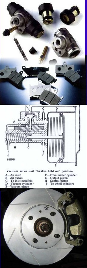
Brake System Overview In today’s modern cars, the typical brake system consists of disk brakes in front and either disk or drum brakes on the rear connected by a system of tubes and hoses that link the brake at each wheel to the master cylinder. Other systems that are connected with the brake system include the parking brakes, power brake booster and the anti-lock system. When you step on the brake pedal, you are actually pushing against a plunger in the master cylinder which forces hydraulic oil (brake fluid) through a series of tubes and hoses to the braking unit at each wheel. Since hydraulic fluid (or any fluid for that matter) cannot be compressed, pushing fluid through a pipe is just like pushing a steel bar through a pipe. Unlike a steel bar, however, fluid can be directed through many twists and turns on its way to its destination, arriving with the exact same motion and pressure that it started with. It is very important that the fluid is pure liquid and that there are no air bubbles in it. Air can compress which causes sponginess to the pedal and severely reduced braking efficiency. If air is suspected, then the system must be bled to remove the air. There are "bleeder screws" at each wheel cylinder and calliper for this purpose.
On a disk brake, the fluid from the master cylinder is forced into a calliper where it presses against a piston. The piston, in-turn, squeezes two brake pads against the disk (another name for disc is rotor) which is attached to the wheel, forcing it to slow down or stop.
This process is similar to a bicycle brake where two rubber pads rub against the wheel rim creating friction.
With drum brakes, fluid is forced into the wheel cylinder which pushes the brake shoes out so that the friction linings are pressed against the drum which is attached to the wheel, causing the wheel to stop.
In either case, the friction surfaces of the pads on a disk brake system, or the shoes on a drum brake convert the forward motion of the vehicle into heat. Heat is what causes the friction surfaces (linings) of the pads and shoes to eventually wear out and require replacement.
Master Cylinder
The master cylinder is located in the engine compartment on the firewall, directly in front of the driver's seat. A typical master cylinder is actually two completely separate master cylinders in one housing, each handling two wheels. This way if one side fails, you will still be able to stop the car. The brake warning light on the dash will light if either side fails, alerting you to the problem. Master cylinders have become very reliable and rarely malfunction; however, the most common problem that they experience is an internal leak. This will cause the brake pedal to slowly sink to the floor when your foot applies steady pressure. Letting go of the pedal and immediately stepping on it again brings the pedal back to normal height.
Brake Fluid
Brake fluid is special oil that has specific properties. It is designed to withstand cold temperatures without thickening as well as very high temperatures without boiling. (If the brake fluid should boil, it will cause you to have a spongy pedal and the car will be hard to stop.) Brake fluid must meet the current standard, which is DOT-3. DOT-3 has a boiling point of 460º F. Always check your owners manual to see what your vehicle manufacturer recommends.
The brake fluid reservoir is on top of the master cylinder. Most cars today have a transparent reservoir so that you can see the level without opening the cover. The brake fluid level will drop slightly as the brake pads wear. This is a normal condition and no cause for concern. If the level drops noticeably over a short period of time or goes down to about two thirds full, have your brakes checked as soon as possible. Keep the reservoir covered except for the amount of time you need to fill it and never leave a can of brake fluid uncovered. Brake fluid must maintain a very high boiling point .Exposure to air will cause the fluid to absorb moisture which will lower that boiling point.
NEVER PUT ANYTHING BUT APPROVED BRAKE FLUID IN YOUR BRAKES. ANYTHING ELSE CAN CAUSE SUDDEN BRAKE FAILURE! Any other type of oil or other fluid will react with the brake fluid and very quickly destroy the rubber seals in the brake system causing brake failure.
Brake Lines
The brake fluid travels from the master cylinder to the wheels through a series of steel tubes and reinforced rubber hoses. Rubber hoses are only used in places that require flexibility, such as at the front wheels, which move up and down as well as steer. The rest of the system uses non-corrosive seamless steel tubing with special fittings at all attachment points. If a steel line requires a repair, the best procedure is to replace the complete line. If this is not practical, a line can be repaired using special splice fittings that are made for brake system repair. You must never use brass "compression" fittings or copper tubing to repair a brake system. They are dangerous and illegal in most countries.
Other Components in the Hydraulic System
Proportioning valve or Equalizer Valve
These valves are mounted between the master cylinder and the rear wheels. They are designed to adjust the pressure between the front and rear brakes depending on how hard you are stopping. The shorter you stop, the more of the vehicle's weight is transferred to the front wheels, in some cases, causing the rear to lift and the front to dive. These valves are designed to direct more pressure to the front and less pressure to the rear the harder you stop. This minimizes the chance of premature lockup at the rear wheels.
Pressure Differential Valve
This valve is usually mounted just below the master cylinder and is responsible for turning the brake warning light on when it detects a malfunction. It measures the pressure from the two sections of the master cylinder and compares them. Since it is mounted ahead of the proportioning or equalizer valve, the two pressures it detects should be equal. If it detects a difference, it means that there is probably a brake fluid leak somewhere in the system.
Combination Valve
The Combination valve is simply a proportioning valve and a pressure differential valve that is combined into one unit.
Disk Brakes
The disk brake is the best brake to have been invented so far for vehicle use. Wet Disk brakes are found on locomotives, earthmoving equipment and jumbo jets. Disk brakes wear longer, are less affected by water, are self adjusting, self cleaning, less prone to grabbing or pulling and stop better than any other system around. The main components of a disk brake are the Brake Pads, Rotor, Calliper and Calliper Support.
Brake Pads
There are two brake pads on each calliper. They are constructed of a metal "shoe" with the lining riveted or bonded to it. The pads are mounted in the calliper, one on each side of the rotor. Brake linings used to be made primarily of asbestos because of its heat absorbing properties and quiet operation; however, due to health risks, asbestos has been outlawed, so new materials are now being used. Brake pads wear out with use and must be replaced periodically. There are many types and qualities of pads available. The differences have to do with brake life (how long the new pads will last) and noise (how quiet they are when you step on the brake). Harder linings tend to last longer and stop better under heavy use but they may produce an irritating squeal when they are applied. Brake pads should be checked for wear periodically. When the lining wears down to the metal brake shoe, you will have a "Metal-to-Metal" condition where the shoe rubs directly against the rotor, causing severe damage and subsequent loss of braking efficiency. Some brake pads come with a "brake warning sensor" that will generate a light on the gauge cluster/instrument cluster. Whenever this light appears you must have your pads checked.
Rotor
The disk rotor is made of iron with highly machined surfaces where the brake pads contact it. Just as the brake pads wear out over time, the rotor also undergoes some wear, usually in the form of ridges and groves where the brake pad rubs against it. This wear pattern exactly matches the wear pattern of the pads as they seat themselves to the rotor. When the pads are replaced, the rotor must be machined smooth to allow the new pads to have an even contact surface to work with. Only a small amount of material can be machined off of a rotor before it becomes unusable and must be replaced. A minimum thickness measurement is stamped on every rotor and the technician doing the brake job will measure the rotor before and after machining it to make sure it doesn't go below the legal minimum. If a rotor is cut below the minimum, it will not be able to handle the high heat that brakes normally generate. This will cause the brakes to "fade," greatly reducing their effectiveness to a point where you may not be able to stop!
Another point worth noting is that sometimes, rotors can result in warping whenever a tyre fitter uses an air gun to rattle on your wheel nuts!
Calliper & Support
There are two main types of callipers: Floating callipers and fixed callipers. There are other configurations but these are the most popular. Callipers must be rebuilt or replaced if they show signs of leaking brake fluid.
Single Piston Floating Callipers are the most popular and also least costly to manufacture and service. A floating calliper "floats" or moves in a track in its support so that it can centre itself over the rotor. As you apply brake pressure, the hydraulic fluid pushes in two directions. It forces the piston against the inner pad which in turn pushes against the rotor. It also pushes the calliper in the opposite direction against the outer pad, pressing it against the other side of the rotor. Floating callipers are also available on some vehicles with two pistons mounted on the same side. Two piston floating callipers are found on more expensive cars and can provide improved braking.
Four Piston Fixed Callipers are mounted rigidly to the support and are not allowed to move. Instead, there are two pistons on each side that press the pads against the rotor. Four piston callipers have a better feel and are more efficient, but are more expensive to produce and cost more to service. This type of calliper is usually found on more expensive luxury and high performance cars.
Drum Brakes
So if disk brakes are so great, how come we still have cars with drum brakes? The reason is cost. While all vehicles produced for many years have disk brakes on the front, drum brakes are cheaper to produce for the rear wheels. The main reason is the parking brake system. On drum brakes, adding a parking brake is the simple addition of a lever, while on disk brakes, we need a complete mechanism, in some cases, a complete mechanical drum brake assembly inside the disk brake rotor! Parking brakes must be a separate system that does not use hydraulics. It must be totally mechanical, more on parking brakes later.
Drum brakes consist of a backing plate, brake shoes, brake drum, wheel cylinder, return springs and an automatic or self-adjusting system. When you apply the brakes, brake fluid is forced, under pressure, into the wheel cylinder which, in turn, pushes the brake shoes into contact with the machined surface on the inside of the drum. When the pressure is released, return springs pull the shoes back to their rest position. As the brake linings wear, the shoes must travel a greater distance to reach the drum. When the distance reaches a certain point, a self-adjusting mechanism automatically reacts by adjusting the rest position of the shoes so that they are closer to the drum.
Brake Shoes
Like the disk pads, brake shoes consist of a steel shoe with the friction material or lining riveted or bonded to it. Also like disk pads, the linings eventually wear out and must be replaced. If the linings are allowed to wear through to the bare metal shoe, they will cause severe damage to the brake drum.
Backing Plate
The backing plate is what holds everything together. It attaches to the axle and forms a solid surface for the wheel cylinder, brake shoes and assorted hardware. It rarely causes any problems unless it rusts through!
Brake Drum
Brake drums are made of iron and have a machined surface on the inside where the shoes make contact. Just as with disk rotors, brake drums will show signs of wear as the brake linings seat themselves against the machined surface of the drum. When new shoes are installed, its ideal that the brake drum should be machined smooth, however, most people will only do this if there are excessive ridges worn into the drum. Brake drums have a maximum diameter specification that is stamped on the outside of the drum. When a drum is machined, it must never exceed that measurement. If the surface cannot be machined within that limit, the drum must be replaced.
Wheel Cylinder
The wheel cylinder consists of a cylinder that has two pistons, one on each side. Each piston has a rubber seal and a shaft that connects the piston with a brake shoe. When brake pressure is applied, the pistons are forced out pushing the shoes into contact with the drum. Wheel cylinders must be rebuilt or replaced if they show signs of leaking.
Return Springs
Return springs pull the brake shoes back to their rest position after the pressure is released from the wheel cylinder. If the springs are weak and do not return the shoes all the way, it will cause premature lining wear because the linings will remain in contact with the drum. A good technician will examine the springs during a brake job and recommend their replacement if they show signs of fatigue. On certain vehicles, the technician may recommend replacing them even if they look good as inexpensive insurance. In this case it’s up to you!
Self Adjusting System
The parts of a self adjusting system should be clean and move freely to insure that the brakes maintain their adjustment over the life of the linings. If the self adjusters stop working, you will notice that you will have to step down further and further on the brake pedal before you feel the brakes begin to engage. Disk brakes are self adjusting by nature and do not require any type of mechanism. When a mechanic performs a brake repair, apart from checking the return springs, he should also clean and lubricate the self adjusting parts where necessary.
Parking Brakes
The parking brake (a.k.a. emergency brake) system controls the rear brakes through a series of steel cables that are connected to either a hand lever or a foot pedal. The idea is that the system is fully mechanical and completely bypasses the hydraulic system so that the vehicle can be brought to a stop even if there is a total brake failure.
On drum brakes, the cable pulls on a lever mounted in the rear brake and is directly connected to the brake shoes. This has the effect of bypassing the wheel cylinder and controlling the brakes directly.
Disk brakes on the rear wheels add additional complication for parking brake systems. There are two main designs for adding a mechanical parking brake to rear disk brakes. The first type uses the existing rear wheel calliper and adds a lever attached to a mechanical corkscrew device inside the calliper piston. When the parking brake cable pulls on the lever, this corkscrew device pushes the piston against the pads, thereby bypassing the hydraulic system, to stop the vehicle. This type of system is primarily used with single piston floating callipers, if the calliper is of the four piston fixed type, then that type of system can't be used.
The other system uses a complete mechanical drum brake unit mounted inside the rear rotor. The brake shoes on this system are connected to a lever that is pulled by the parking brake cable to activate the brakes. The brake "drum" is actually the inside part of the rear brake rotor.
On cars with automatic transmissions, the parking brake is rarely used. This can cause a couple of problems. The biggest problem is that the brake cables tend to get corroded and eventually seize up causing the parking brake to become inoperative. By using the parking brake from time to time, the cables stay clean and functional. Another problem comes from the fact that the self adjusting mechanism on certain brake systems uses the parking brake actuation to adjust the brakes. If the parking brake is never used, then the brakes never get adjusted.
Power Brake Booster/Servo
The power brake booster is mounted on the firewall directly behind the master cylinder and, along with the master cylinder, is directly connected with the brake pedal. Its purpose is to amplify the available foot pressure applied to the brake pedal so that the amount of foot pressure required to stop even the largest vehicle is minimal. Power for the booster comes from engine vacuum. The automobile engine produces vacuum as a by-product of normal operation and is freely available for use in powering accessories such as the power brake booster. Vacuum enters the booster through a check valve on the booster. The check valve is connected to the engine with a rubber hose and acts as a one-way valve that allows vacuum to enter the booster but does not let it escape. The booster is an empty shell that is divided into two chambers by a rubber diaphragm. There is a valve in the diaphragm that remains open while your foot is off the brake pedal so that vacuum is allowed to fill both chambers. When you step on the brake pedal, the valve in the diaphragm closes, separating the two chambers and another valve opens to allow air in the chamber on the brake pedal side. This is what provides the power assist.
Power boosters are very reliable and cause few problems of their own, however, other things can contribute to a loss of power assist. In order to have power assist, the engine must be running. If the engine stalls or shuts off while you are driving, you will have a small reserve of power assist for two or three pedal applications but, after that, the brakes will be extremely hard to apply and you must put as much pressure as you can to bring the vehicle to a stop.
Anti-Lock Brakes (ABS)
The most efficient braking pressure takes place just before each wheel locks up. When you slam on the brakes in a panic stop and the wheels lock up, causing a screeching sound and leaving strips of rubber on the tarmac, you do not stop the vehicle nearly as short as it is capable of stopping. Also, while the wheels are locked up, you loose all steering control so that, if you have an opportunity to steer around the obstacle, you will not be able to do so. Another problem occurs during an extended skid is that you will burn a patch of rubber off the tire which causes a "flat spot" on the tread that will produce an annoying thumping sound as you drive.
Anti-lock brake systems solve this lockup problem by rapidly pumping the brakes whenever the system detects a wheel that is locked up. In most cases, only the wheel that is locked will be pumped, while full braking pressure stays available to the other wheels. This effect allows you to stop in the shortest amount of time while maintaining full steering control even if one or more wheels are on ice. The system uses a computer to monitor the speed of each wheel. When it detects that one or more wheels have stopped or are turning much slower than the remaining wheels, the computer sends a signal to momentarily remove and reapply or pulse the pressure to the affected wheels to allow them to continue turning. This "pumping" of the brakes occurs at ten or more times a second, far faster then a human can pump the brakes manually. If you step on the brakes hard enough to engage the anti-lock system, you may feel a strong vibration in the brake pedal. This is a normal condition and indicates that the system is working. However, this vibration can be a shock to some people who don't expect it. If your vehicle has anti-lock brakes, read your owner's manual to find out more about it.
The system consists of an electronic control unit, a hydraulic actuator and wheel speed sensors at each wheel. If the control unit detects a malfunction in the system, it will illuminate an ABS warning light on the dash to let you know that there is a problem. If there is a problem, the anti-lock system will not function but the brakes will otherwise function normally.
|
|
|
|
|
|
|
|
|
|
|
|
|
|
|
|
|
|
|
|
|
|
|
|
|